This document covers the necessary steps to create a simple LabVIEW application by using the IC LabVIEW extension to grab IMAQ images.
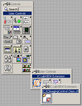
Create a blank VI, select IC Imaging Control from the User Library palette and drag it on to the Front Panel.
If the entry "IC.IC Imaging Control Class.ctl" does not appear in your palette, it needs to be created first. Ensure you have IC Imaging Control 1.41 or later installed on your computer. Select Tools -> Advanced -> Import ActiveX Controls... and choose IC.IC Imaging Control Class. After clicking OK, a File Save Dialog appears. Save the LabVIEW Control Container in your user.lib directory.
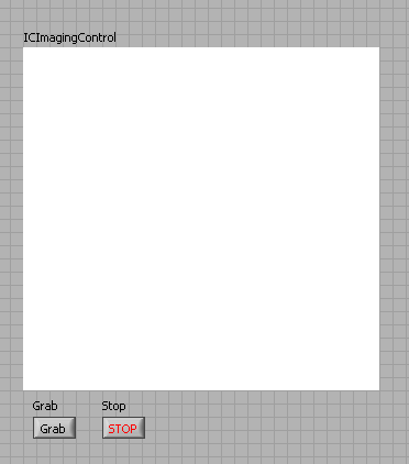
Place 2 buttons on the Front Panel, and label them "Grab" and "Stop".
Now your Front Panel should look like this:
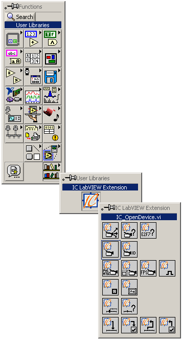
You can switch to the Block Diagram view to add additional functionality.
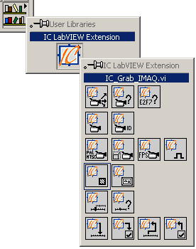
Select the IC_OpenDevice VI from the User Library palette:
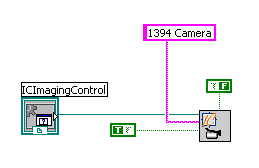
Drag it on to the Block Diagram and connect its "IC Imaging Control in" input to IC Imaging Control on the Block Diagram.
In this example, we will grab monochrome (8-bit) images. Therefore, create a Boolean constant, set it to false and connect it to the "Color" input of IC_OpenDevice.
Create another Boolean constant, set it to true and connect it to the "Live" input of IC_OpenDevice. By doing this, we make sure IC Imaging Control is in live mode, thus allowing fast image grabbing.
Create a string constant and connect it to the "Device" input of IC_OpenDevice. Change the constant's value to the name of the device you want to use. The name must be identical to the name that appears in IC Capture or in the device list of IC Imaging Control demo applications. In this example, we use "1394 Camera". Please, make sure you enter the correct name for your device here - otherwise, the VI we are building will not work. If you do not know the name of your device, you can insert IC_GetDevices (from the User Library palette). It returns an array with the names of the devices installed on your system.
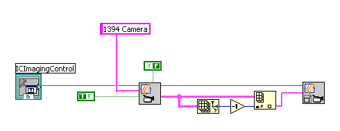
Your Block Diagram should now look like this:
Now we specify a video format for the device. IC_OpenDevice returns an array of valid video formats for the opened device. For this example, we just select the last entry in the list, assuming the larger formats are towards the end.
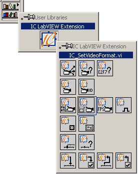
Select IC_SetVideoFormat from the User Library palette and place it on the Block Diagram.
After adding the necessary wires, the Block Diagram should look like this:
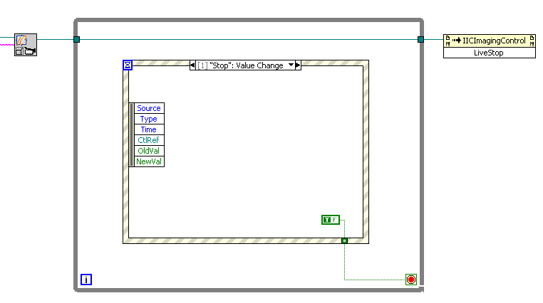
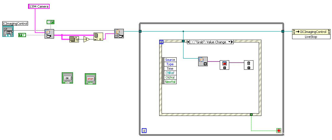
IC Imaging Control is now able to display a live image from the device we previously selected. As the VI will not run continually, it is necessary to insert a While Loop into the Block Diagram. In order to be able to handle events, such as the user clicking on the Stop button, we need to insert an Event Structure into the While Loop.
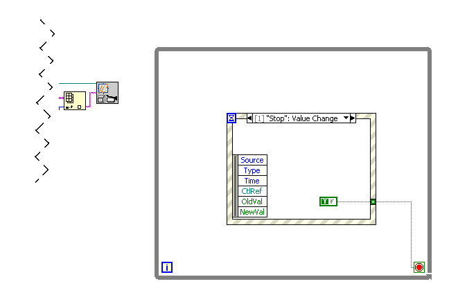
To enable the Stop button, add an Event Case to the Event Structure. In the "Edit Events" dialog, select the Stop button and the event "Value Change". Insert a Boolean constant into the new Event Frame, set it to true and connect it to the While Loop's exit condition.
When the application ends, the opened device should be taken out of live mode (using the StopLive method of IC Imaging Control). Failure to do this will result in the device continuing to send images to IC Imaging Control - even in LabVIEW's edit mode.
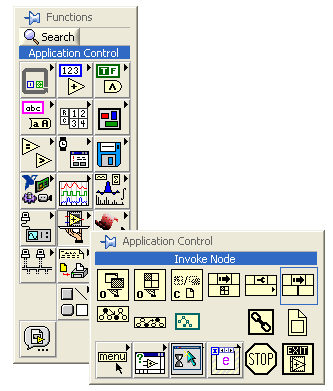
First, insert an Invoke Node:
Connect the Reference input of the Invoke Node with the "IC Imaging Control out" output of the IC_SetVideoFormat VI, ensuring the wire leads through the While Loop. Failure to do so, will stop live mode before the loop is executed.
You will notice that the size of the Invoke Node changes when connecting the wire. Click on "Method" and select "LiveStop".
You can now run the first test. Switch to Front Panel view, and click on "Run". If the application is set up properly, you will see a live image from the selected device. Otherwise, an error message such as the following will appear.

The message shown above indicates that an incorrect name was used to specify the video capture device. In this case click on "Stop", go back to step 3 and make sure you enter the correct string to specify the device.
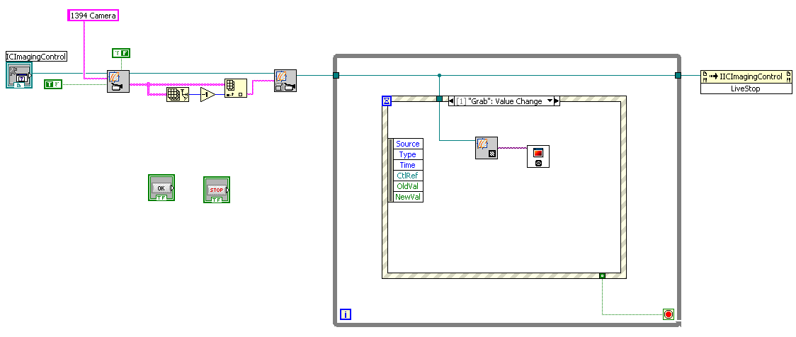
Add the event "Value Change" to the Grab button and insert the IC_Grab_IMAQ VI. You can also use the IC_Grab_Picture VI if you do not have the IMAQ library installed.
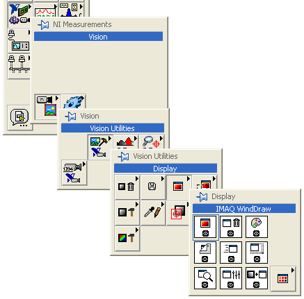
The IC_Grab_IMAQ VI grabs an image from the device that is currently open in IC Imaging Control and puts the data into an IMAQ image. To display the image, we use the IMAQ WindDraw VI from the IMAQ library:
Your Block Diagram should now look like this:
You can now run the application and try the grab function. You will, however, notice that the application uses an increasing amount of memory every time an image is grabbed. To solve this problem, you have to delete the IMAQ images, using the IMAQ Dispose VI.
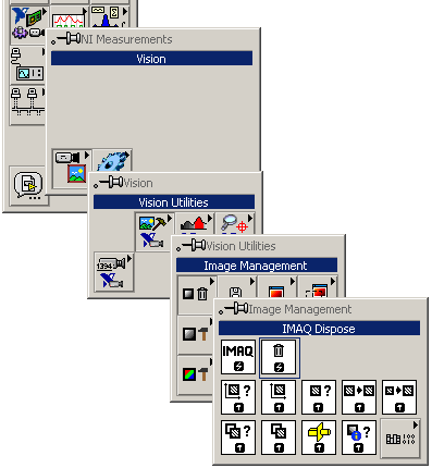
Insert the IMAQ Dispose VI into your application:
Further issues to consider: